
Case study · Surge analysis
Surge analysis & air vessel sizing: Al Bedai pumping station and transmission mains
Transient analysis of a large potable water pumping station and its two transmission mains, covering power failure, valve closure and tank level cases across present and future demand. The study sized the closed air vessels and set their air-charge control philosophy.
Client
Sharjah Electricity, Water & Gas Authority (SEWA)
Location
Al Bedai, UAE
Scope
Power failure, valve closure, air vessel sizing
Tools
Bentley HAMMER
Criteria
Min. −0.4 barg · within 16 barg pipe rating
−0.94 → −0.31 barg
Minimum pressure without vs with protection
2 × 83.9 m³
Closed air vessels, one per pumping main
8 scenarios
Demand, tank level and roughness matrix
56%
Peak upsurge as a share of pipe design pressure
The challenge
Column separation on two long mains
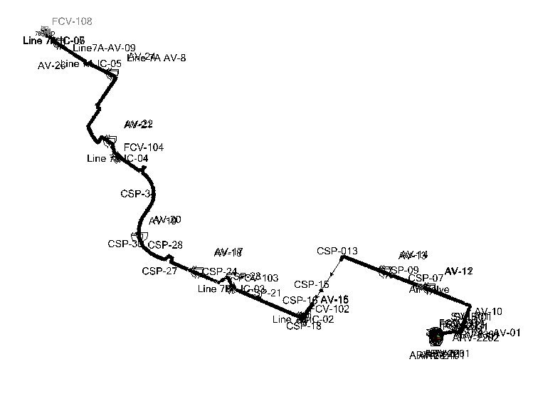
A power failure at the station would stop the flow in the two transmission mains, which supply interconnections and a remote reservoir. Without protection, pressures fall to vapour pressure on one line and the water column separates. Air valves alone were not enough, so the station needed vessels sized for every demand, tank level and pipe roughness case.
Our approach
Transient analysis
- HAMMER model of the pumping station, suction system and both transmission mains, including air valves and flow control valves
- Power failure checked without protection, with air valves only, and with air vessels
- Eight-case matrix: present and future demand, high and low tank level, new and aged pipe roughness
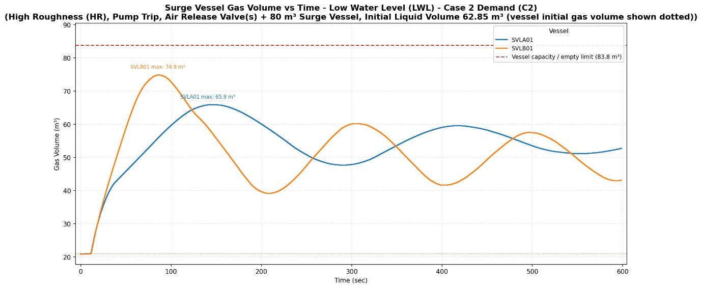
- Air vessel volume and initial liquid volume optimised between loss of water seal and excessive downsurge
- Simultaneous closure of all flow control valves checked for the maximum upsurge
- Air-charge control and compressor duty specified
Results
Key results
Key findings
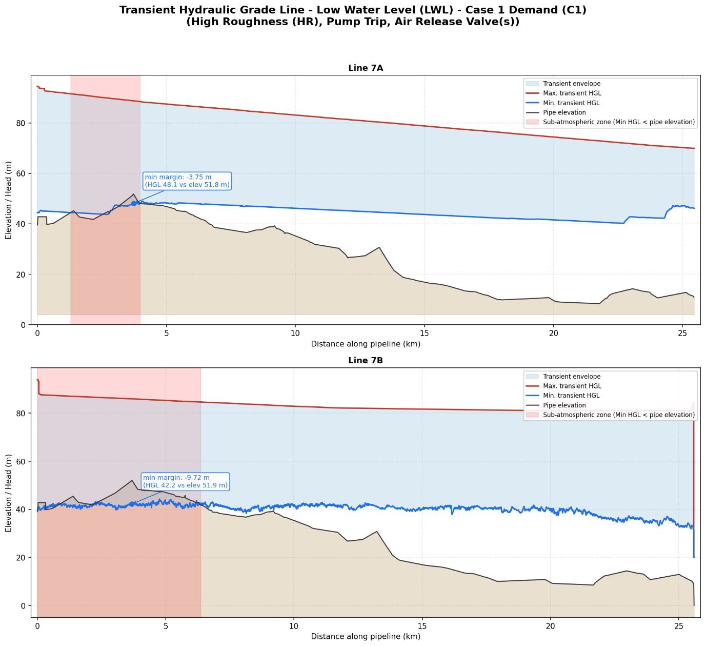
- Unprotected, the mains fall to −0.94 barg and the water column separates on one line, so positive protection is needed.
- With air valves only, pressures still fall to −0.52 barg in the future demand case, below the −0.4 barg limit.
- One 83.9 m³ closed air vessel per main, charged to 62.85 m³ of water, keeps the minimum at −0.31 barg across all eight cases, with no column separation.
- The initial water volume is bounded from both sides: more air risks losing the water seal, and more water lets the downsurge breach the limit.
- Closing all flow control valves together gives a peak of 8.93 barg, 56% of the pipe design pressure.
- Air-charge control by air mass, not water level, is specified to keep the vessel at its design cushion.
Working on a similar project?
Share your pump station data, pipeline profile and valve details and we will advise on the right surge analysis scope.