
Case study · Tank mixing CFD
CFD study of a 20 MIG water storage tank: mixing, stratification & chlorine, Al Ain
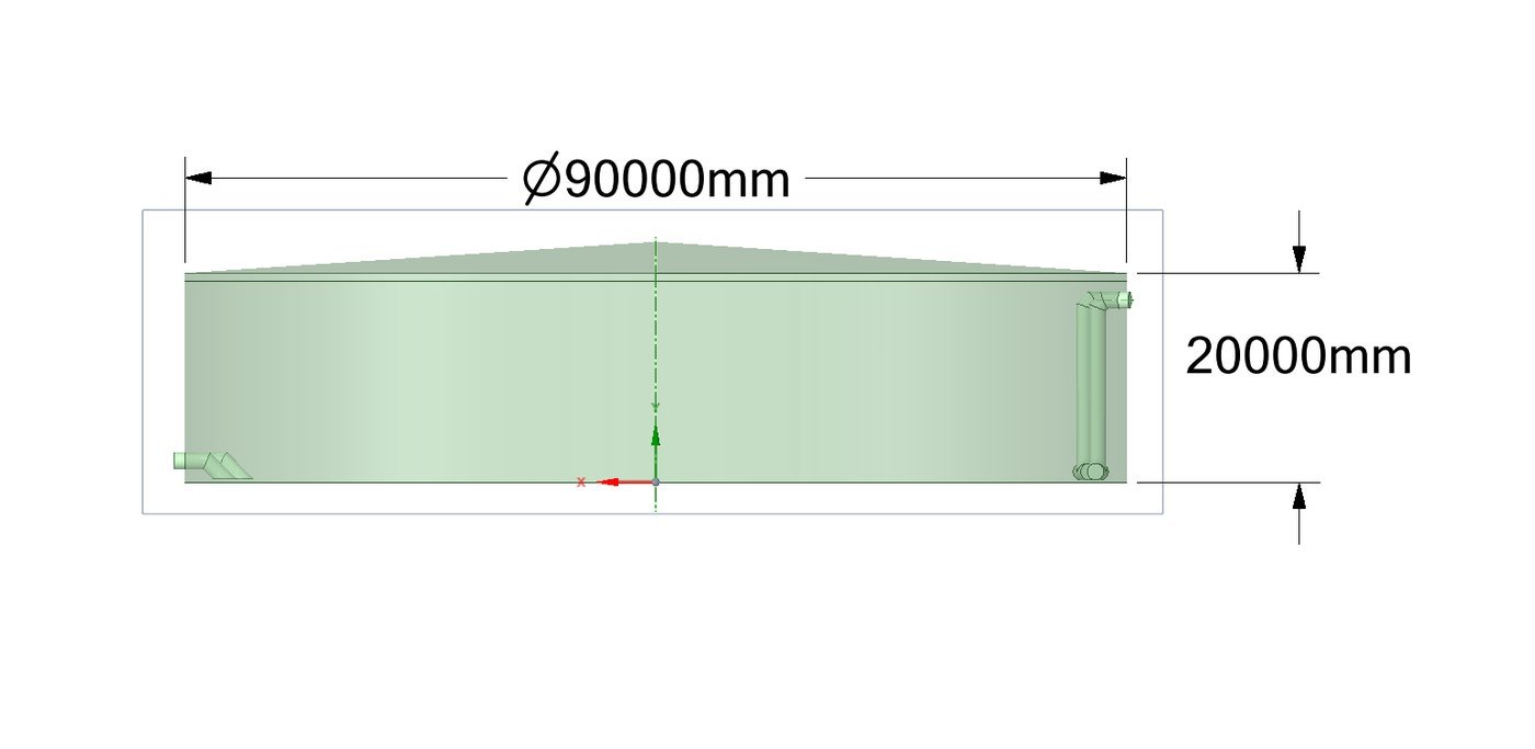
CFD of a 90 m diameter, 20 m high potable water storage tank, covering hydraulic efficiency, dead zones, thermal stratification and chlorine decay. An inlet modification was tested to remove zones where the residual dropped to zero.
Client
TAQA
Location
Al Ain, Abu Dhabi, UAE
Scope
RTD and hydraulic efficiency, dead zones, stratification, chlorine
Tools
ANSYS Fluent: k–ω, UDS tracer, Boussinesq, VOF, species
Asset
20 MIG tank, Ø 90 m × 20 m
≈ 25 h
Theoretical residence time (8.86 × 10⁴ s)
MI 39
Morrill index from CFD tracer RTD (poor mixing)
2 inlets
Modified inlet arrangement with 45° reducers tested
0 → 0.05 mg/L
Minimum internal chlorine, original vs modified
The challenge
A very large tank in a very hot climate
In a tank this size, water entering near the outlet can short-circuit while large volumes stagnate. In Al Ain, solar gain on the roof heats the top layer of water, which can form stable layers that do not mix. Stagnant, warm zones lose chlorine, so the outlet residual alone does not show whether water inside the tank stays protected.
Our approach
CFD methodology
- 3D model of the tank, inlet and outlet pipework built in ANSYS SpaceClaim, with a Fluent mesh refined at the pipes using inflation layers
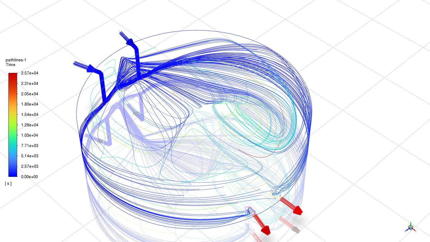
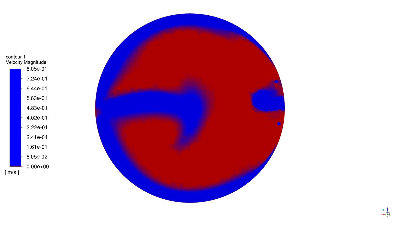
- Steady-state flow with k–ω turbulence, then pathlines, velocity fields and dead zones (velocity below 2% of maximum)
- Transient tracer (user-defined scalar) injected at the inlet to compute the residence time distribution and hydraulic efficiency indices
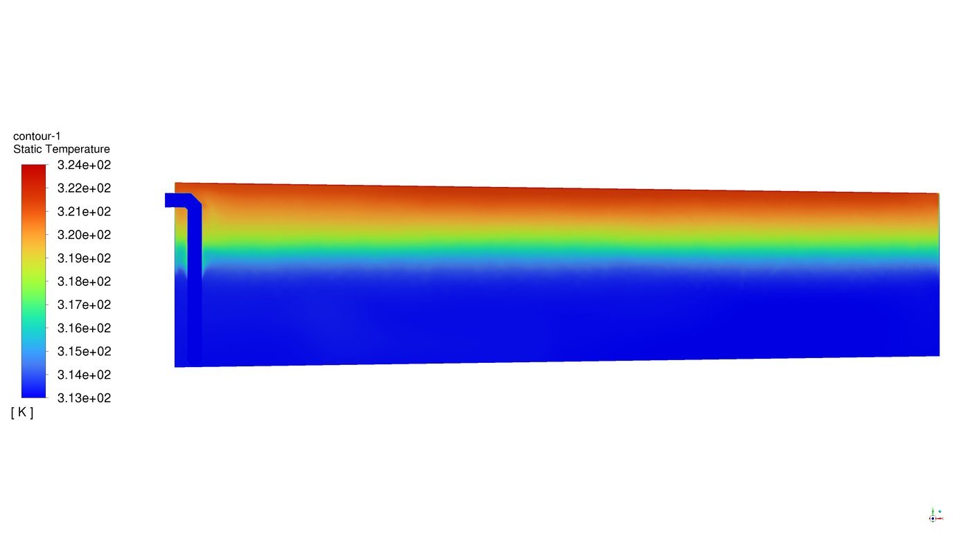
- Thermal stratification with Boussinesq buoyancy and heated roof and wall boundaries, plus a two-phase (VOF) check with the air space above the water
- Chlorine decay as a reacting species with bulk decay of 0.06 day⁻¹ and 0.5 mg/L dosing at the inlet, verified against the plug-flow theoretical value
- Original and modified inlet arrangements compared at average and low flow
Results
Key results
Key findings
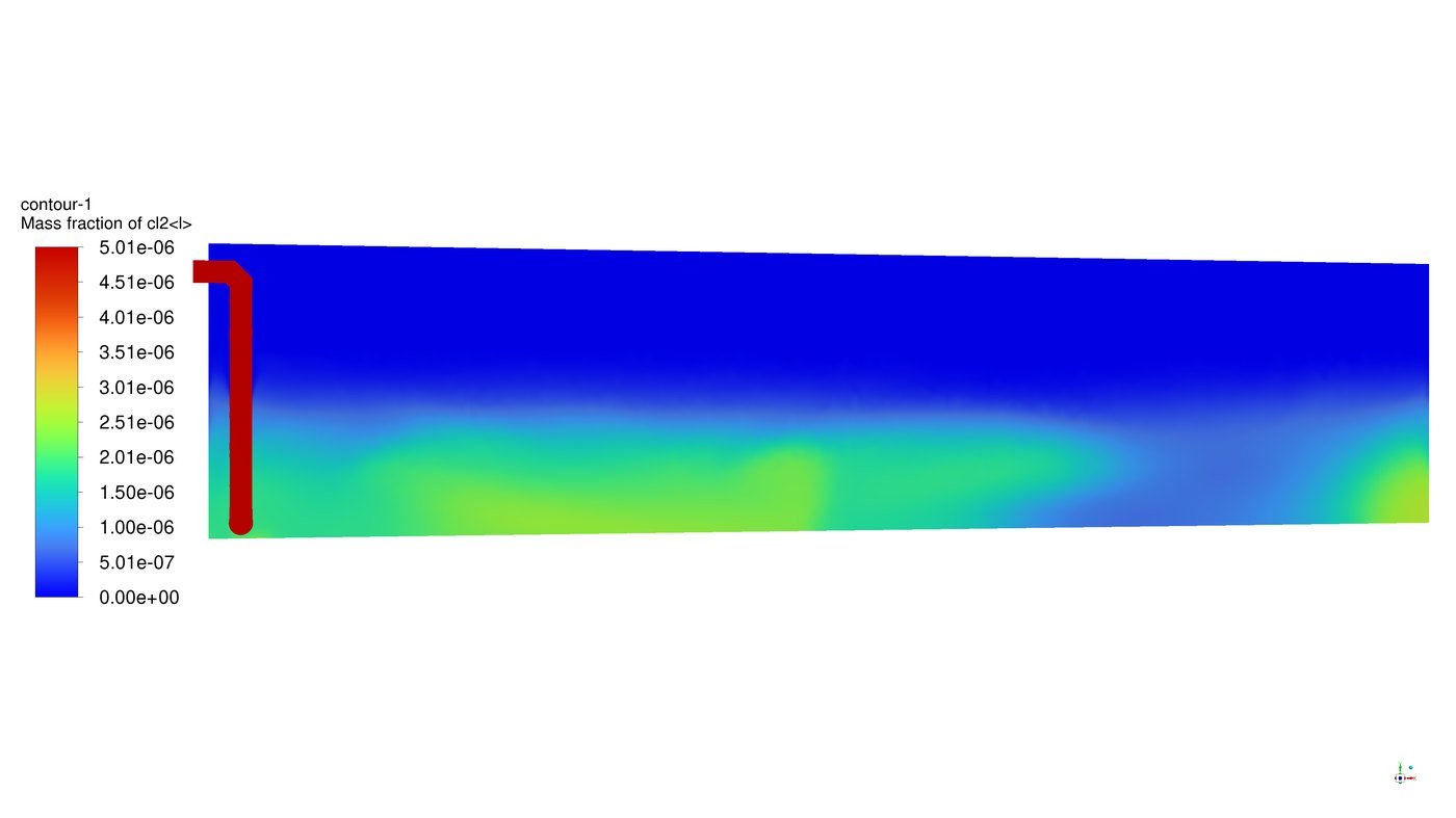
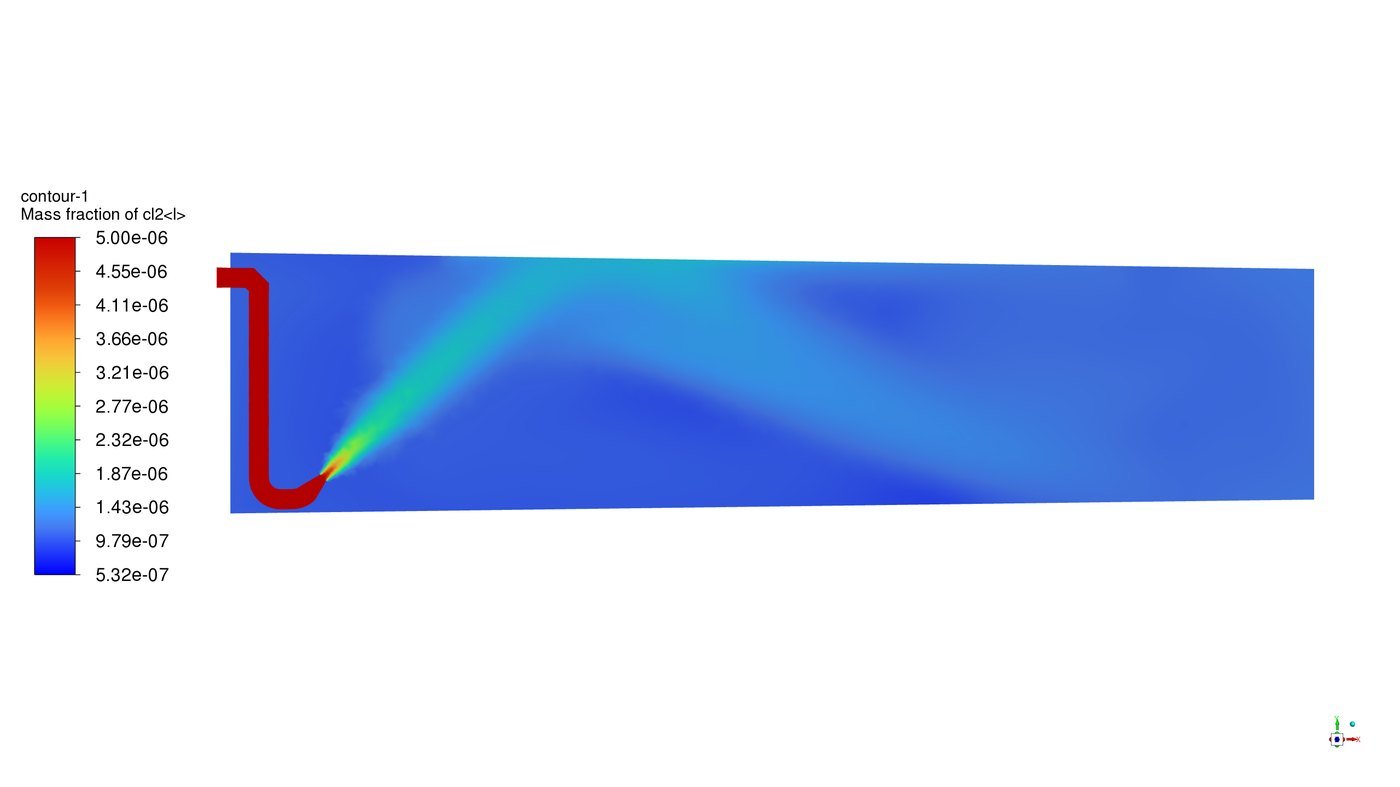
- Strong recirculation, with most of the tank volume classed as dead zone in the original arrangement.
- The tracer RTD gives θ10 = 0.06 and a Morrill index of 39, both rated poor: the tank behaves far from plug flow.
- With heated roof and walls, a stable warm layer forms at the top. The two-phase run shows the air space limits direct heating of the water.
- Original inlet: outlet residual of 0.23 mg/L meets the 0.2 mg/L requirement, but chlorine drops to zero inside the tank.
- Modified inlet (two lines with 45° reducers): internal chlorine never reaches zero (minimum about 0.05 mg/L), but the outlet residual falls to 0.12 mg/L at average flow, so the dosing set point must be reviewed together with the change.
- The species model matches the theoretical first-order decay to within about 1%, confirming the set-up.
Working on a similar project?
Share your drawings, flows and design questions and we will advise on the right CFD scope.