
Case study · CFD of wastewater structures
CFD study of an STP inlet screening building: Warsan, Dubai
Three-dimensional CFD of the coarse and fine screening building at a large sewage treatment plant. It assesses flow distribution across the screening channels, recirculation and dead zones, and where solids are likely to settle, then recommends improvements.
Client
Dubai Municipality
Location
Warsan STP, Dubai, UAE
Scope
Flow distribution, recirculation, sediment risk
Tools
ANSYS Fluent: k–ω SST, porous jump, DPM
Design flow
505 MLD average flow (baseline)
505 MLD
Average design flow modelled (baseline case)
1.91 M cells
Polyhedral mesh, refined at screens and outlet chamber
Porous jump
Screen losses calibrated to manufacturer data
DPM
Particle tracking to locate sediment-prone zones
The challenge
Even flow across parallel screening channels
Raw sewage arrives through gravity sewers and must split evenly between parallel trains of coarse and fine screens. Uneven flow overloads some screens and leaves others under-used, and slow zones collect grit and solids. The client needed to know how the existing arrangement performs and where it should be improved.
Our approach
CFD methodology
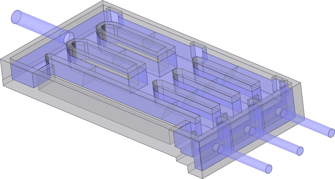
- Full hydraulic path modelled: inlet and outlet sewers, distribution and outlet chambers, screening channels and guide walls
- Half-domain model with a symmetry plane, where the layout allowed, to save about 50% of the cells
- Pressure-based steady-state solver with k–ω SST turbulence and gravity
- Coarse and fine screens represented by porous-jump zones calibrated to the manufacturer’s head-loss data, and validated on a test channel first
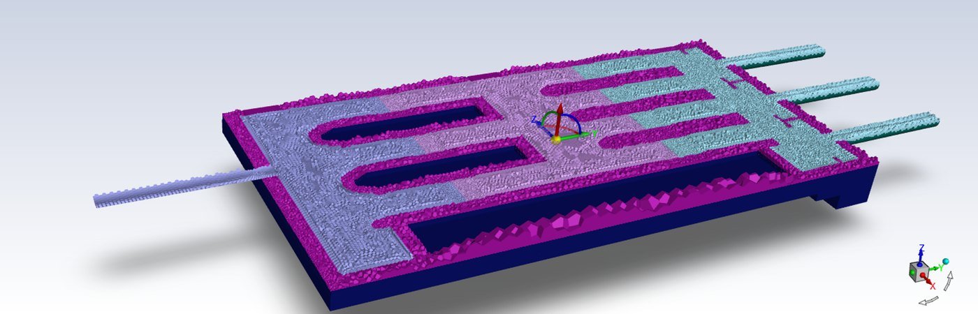
- Polyhedral mesh of 1.91 million cells, refined around screens, junctions and the outlet chamber
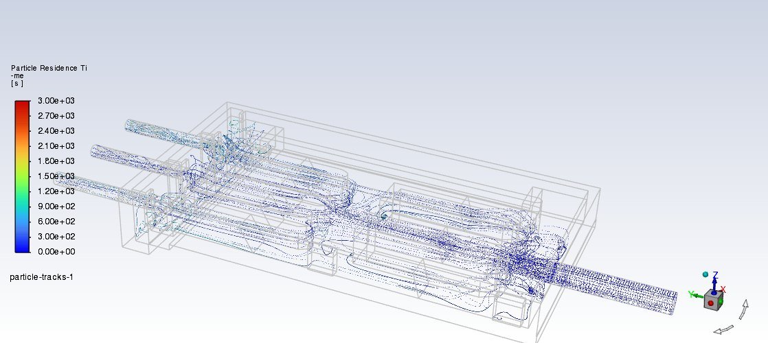
- Suspended solids at 100 mg/L tracked with the Discrete Phase Model to find where particles linger and settle
Results
Key results
Key findings
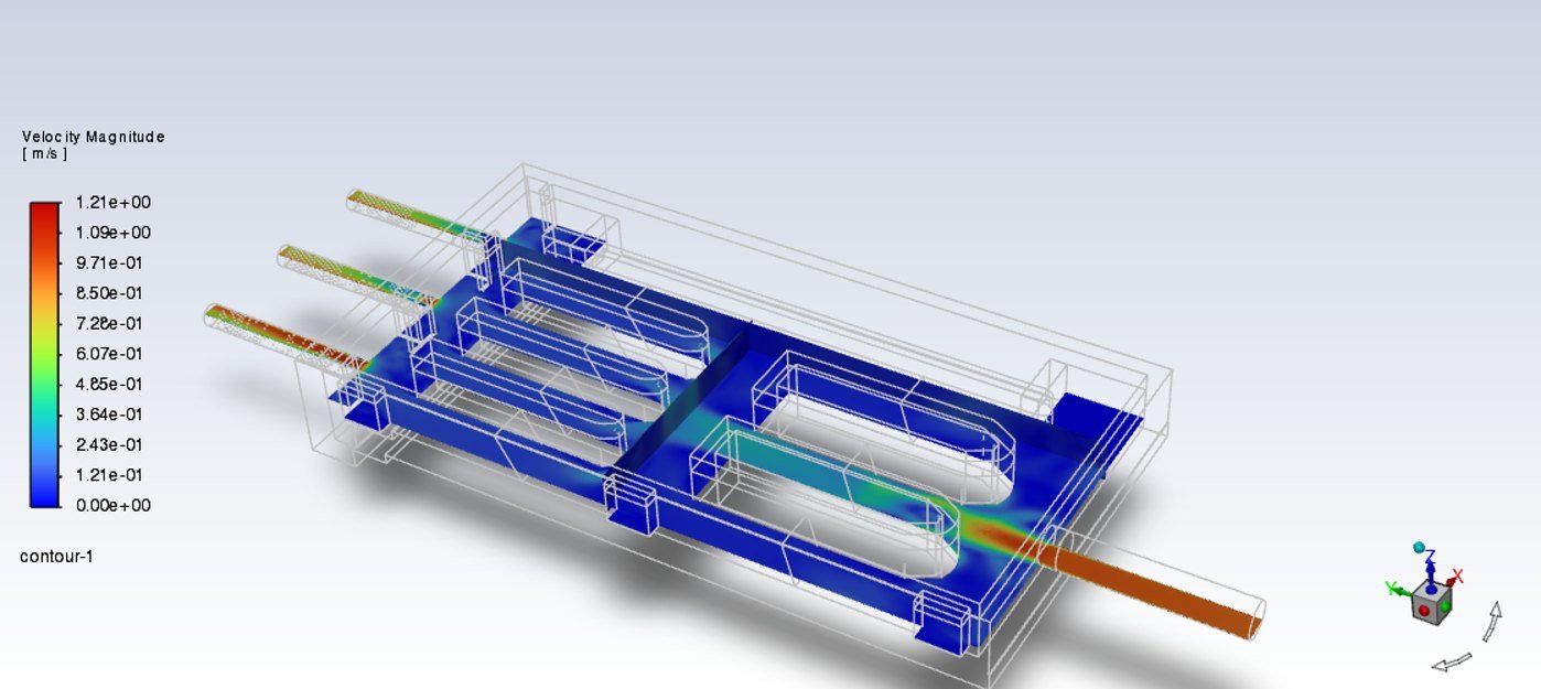
- The design flow arrives smoothly, with no separation upstream, and turns cleanly around the guide walls.
- Screen head loss is reproduced within the manufacturer’s range, and both trains stay in service at design flow.
- Flow is biased toward the central channel, so the side channels are under-loaded and the screens unevenly used.
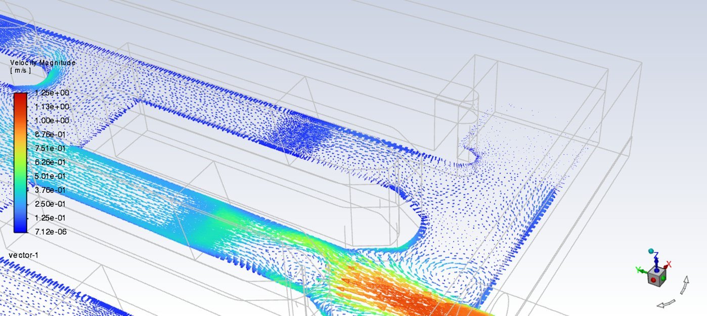
- Recirculation in the outlet chamber and vortices at the splitter walls create low-velocity zones where particles linger longest, the main sediment risk.
- Recommendation: add baffling or rearrange the internal channels to even out the flow, and inspect and clean the outlet chamber regularly.
Working on a similar project?
Share your drawings, flows and design questions and we will advise on the right CFD scope.