
Services · CFD studies · UAE & GCC
CFD study services for water & wastewater assets
We carry out CFD studies of storage tanks, reservoirs, pump intakes, manifolds and wastewater structures for utilities, consultants and EPC contractors. Our models quantify mixing, water age, flow distribution, vortices and sediment risk using ANSYS Fluent. We deliver studies across the UAE, the wider GCC and internationally.
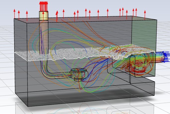
Tanks & reservoirs
Mixing, water age, COV, baffle factor and stratification
Pump intakes & manifolds
Approach flow, vortices, swirl and flow split
Wastewater structures
Screening channels, flow distribution and sediment
Why it matters
Why a CFD study matters
One-dimensional hydraulic models assume water is well mixed and flow divides evenly. Inside real tanks, sumps and channels it rarely does. Short-circuiting, dead zones, vortices and uneven flow split cause poor water quality, pump damage and sediment build-up, and these problems are expensive to fix after construction.
A CFD study shows exactly where these problems occur and tests the fix on screen, before concrete is poured or equipment is ordered.
A well-scoped CFD study allows you to:
- Find short-circuiting, dead volumes and thermal stratification in tanks and reservoirs
- Quantify water age, residence time distribution, COV and baffle factor
- Check pump intake approach flow, swirl and vortex risk before building
- Confirm the flow split across manifolds, channels and parallel trains
- Compare baffles, inlet and outlet arrangements and other fixes before construction
Scope of services
What a CFD study includes
01
Tanks & reservoirs
- Mixing and water age (CFD residence time)
- COV and baffle factor for contact tanks
- Temperature stratification in hot climates
- Inlet, outlet and baffle optimisation
02
Pump intakes & manifolds
- Sump approach flow and velocity uniformity
- Free-surface and submerged vortex screening (VOF)
- Swirl angle at the pump bell
- Flow split in suction and discharge manifolds
03
Wastewater & process structures
- Screening and distribution channels
- Recirculation and dead-zone mapping
- Sediment risk by particle tracking (DPM)
- Comparison of design enhancements
Recent projects
CFD projects in the UAE
-
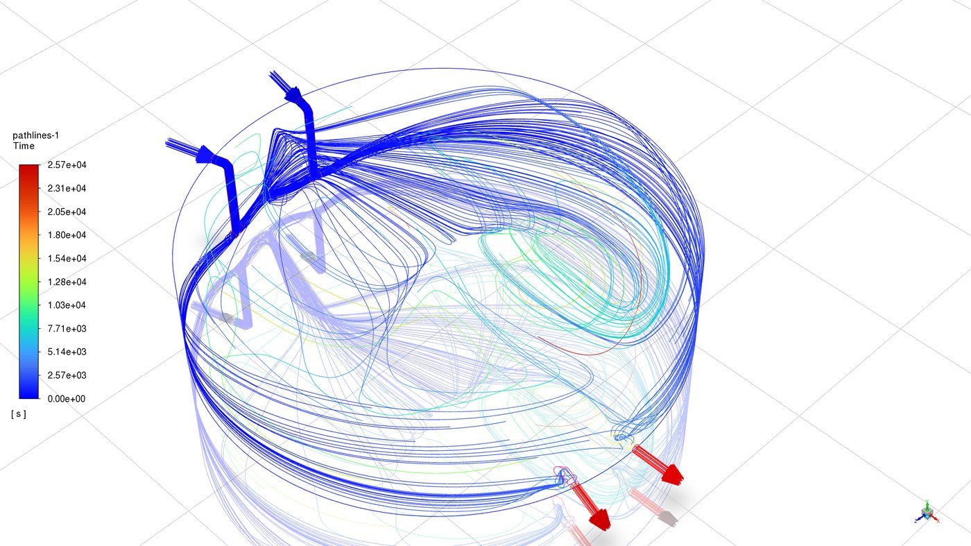
CFD study of a 20 MIG water storage tank: mixing, stratification & chlorine, Al Ain
CFD of a 90 m diameter potable water tank: tracer residence time and dead zones, roof-driven thermal stratification and chlorine decay, with an inlet change tested to keep…
-
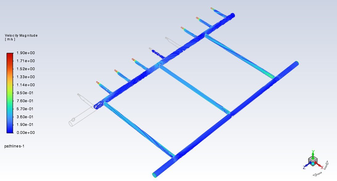
CFD study of a pump suction manifold: Al Bedai tanks & pumping station
Fluent CFD of a common pump suction manifold confirming an even flow split between six duty pumps (within 1%), with mesh-independent results and no geometry change required.
-
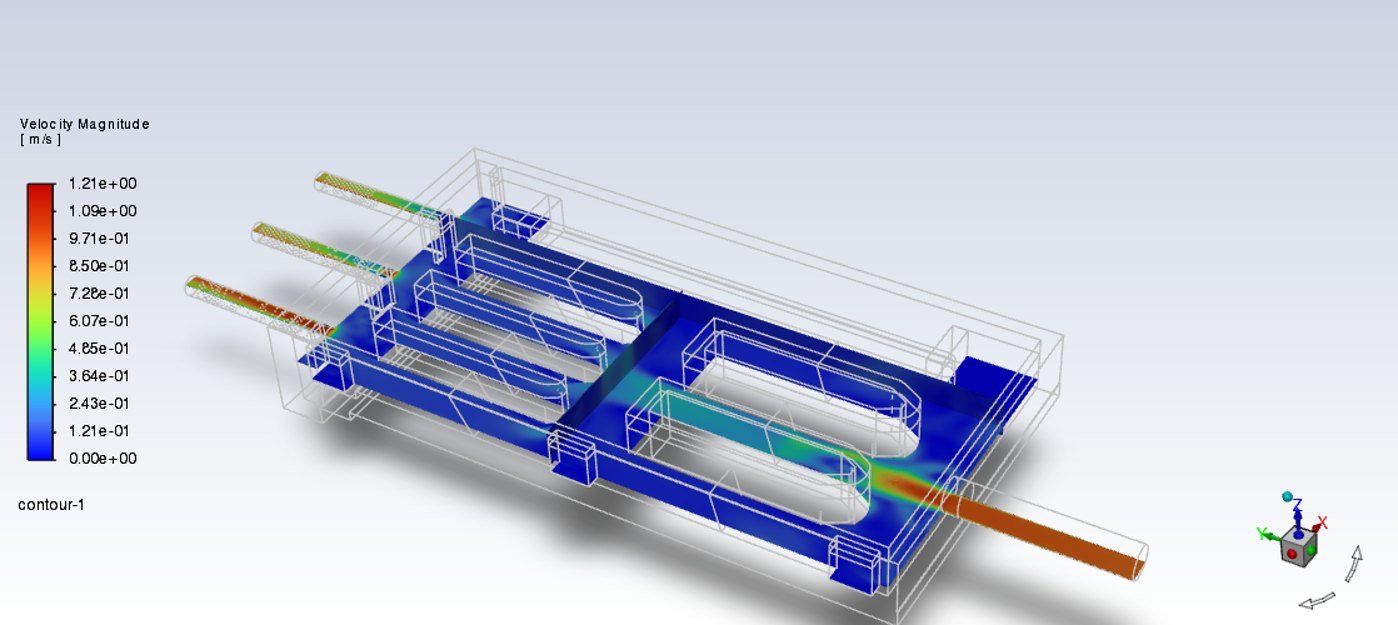
CFD study of an STP inlet screening building: Warsan, Dubai
ANSYS Fluent CFD of a 505 MLD screening building covering flow distribution, recirculation and particle tracking to locate sediment-prone zones, with design improvements recommended.
Process
How we work with you
STEP 01
Brief & data
We agree the questions the CFD must answer, the flow cases and the acceptance criteria, and collect 3D/CAD and manufacturer data.
STEP 02
Modelling & validation
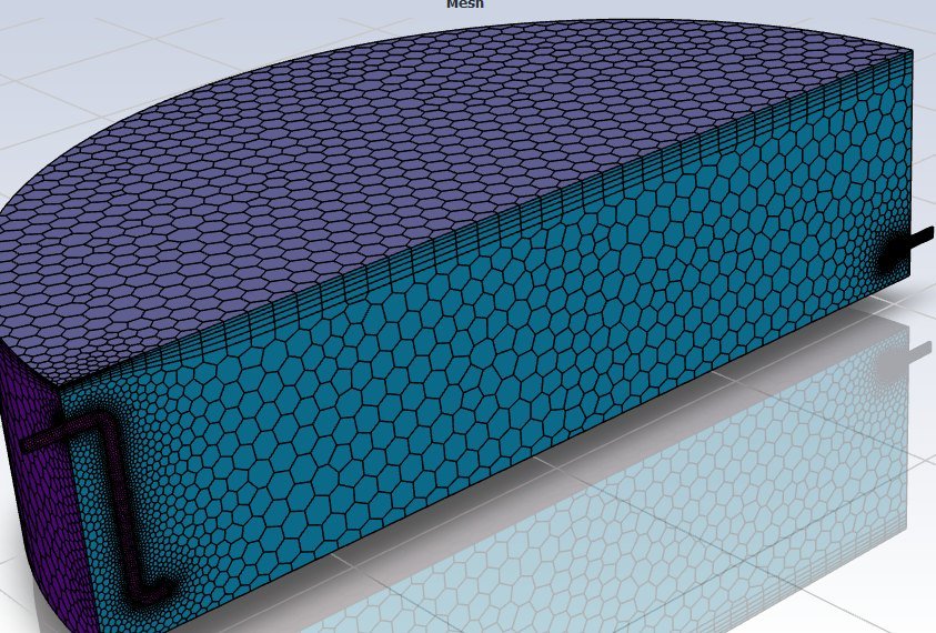
We build and mesh the model, check mesh sensitivity, calibrate screens or losses against manufacturer data, and run the agreed cases.
STEP 03
Recommendations & handover
We report findings with clear contours, pathlines and metrics, compare improvement options, and hand over files on request.
Outputs
Typical deliverables
Each CFD study is scoped to the decision you need to make. Typical outputs include:
- CFD study report with methodology, validation and findings
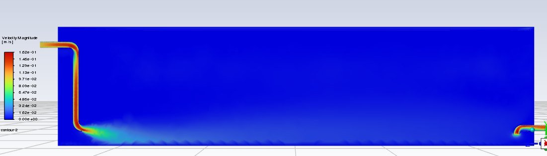
- Velocity, pathline and vector plots at key planes
- Metrics: flow split, water age, COV, baffle factor or swirl angle
- Option comparison of baseline against improved designs
- Mesh sensitivity and convergence evidence for reviewers
Tools & methods
Tools and methods
We use industry-standard CFD software and best-practice verification, so results stand up to client and authority review.
| Software | ANSYS Fluent and CFX |
| Turbulence | k–ω SST and k–ε RANS models with appropriate wall treatment |
| Physics | VOF free surface, DPM particle tracking, buoyancy and heat transfer, porous media |
| Verification | Mesh sensitivity, convergence monitoring, calibration to manufacturer data |
| Related studies | Water quality modelling and surge analysis |
FAQ
CFD study FAQs
When is a CFD study needed instead of a 1D hydraulic model?
When the answer depends on how water moves inside a structure, for example mixing and water age in a tank, vortices at a pump intake, or how flow splits between closely spaced branches. A 1D model assumes ideal mixing and splits, while CFD resolves the actual 3D flow.
Which software do you use for CFD studies?
We use ANSYS Fluent (and CFX where required), with turbulence, free-surface (VOF), particle tracking (DPM) and heat-transfer models chosen for each problem.
How do you make sure the CFD results are reliable?
Every study includes a mesh sensitivity check and convergence monitoring, and where possible we calibrate against manufacturer or measured data. For example, screen head losses are matched to manufacturer curves before they are used in the full model.
Can CFD replace a physical model for a pump intake?
For many intakes, CFD is an efficient way to screen designs against intake design criteria and compare options. For very large or unusual intakes, the applicable standard or the client may still require a physical model, and CFD then helps optimise the geometry before testing. See our suction manifold case study.