CFD studies for water tanks, reservoirs & pump intakes
We support water utilities, consultants and EPC contractors across the UAE with three-dimensional CFD studies to quantify mixing, residence time, dead zones, temperature stratification, velocity distribution and swirl around pump intakes. Our work helps you validate new designs, troubleshoot operational issues and de-risk major capital projects with defensible engineering evidence.
- Water storage tank CFD for service reservoirs, clear-wells and ground-storage tanks
- Pump intake study for intake structures and wet wells with multiple operating pumps
- Contact tanks, baffled channels and bespoke mixing structures (including COV, baffle factor, and temperature stratification)
Why CFD studies are essential for tanks and pump intakes
Conventional design methods and 1D hydraulic models cannot fully capture three-dimensional effects such as short-circuiting, dead zones, recirculation, temperature stratification and swirl at pump intakes. CFD provides a detailed picture of flow behaviour, helping you avoid poor mixing, air entrainment, vibration and unreliable water-quality performance.
A well-scoped CFD study can help you:
- Identify short-circuiting, dead volumes and stratification in tanks and reservoirs
- Quantify residence time distribution (RTD), water age, and mixing metrics such as COV and baffle factor
- Assess intake approach flow, velocity uniformity and swirl at pump bells
- Compare baffling, inlet/outlet arrangements and mixing devices before construction
- Support design approvals, troubleshooting and optimisation of existing assets
What is a CFD study in water infrastructure?
Computational Fluid Dynamics (CFD) is a numerical method that simulates three-dimensional flow behaviour in tanks, reservoirs and intake structures. It provides visibility of how water actually moves inside an asset: pathlines, recirculation zones, mixing performance, residence time distribution, swirl at intakes and the risk of short-circuiting or stagnant volumes.
For water storage and pumping assets, CFD is typically used to answer practical questions that cannot be resolved reliably using conventional rules-of-thumb or 1D models.
Our CFD study methodology
We execute CFD studies with an engineering-first approach: scoped to the decisions you need to make, with transparent assumptions and clear outputs that design teams and operators can use.
- Confirm objectives, constraints and acceptance criteria (mixing, RTD, COV/baffle factor, intake velocities, swirl, etc.)
- Build or clean geometry from drawings/models and define inlets, outlets, baffles, weirs, pump bells and water levels
- Develop a mesh strategy appropriate to the flow physics and required accuracy
- Run steady-state and/or transient simulations, including scalar transport for age/mixing where relevant
- Post-process into decision-ready metrics, plots and practical recommendations
What we offer in a CFD study
1. Geometry & boundary conditions
- Clean-up and idealisation of tank, reservoir or intake geometry
- Definition of inlets, outlets, weirs, baffles and pump bells
- Selection of operating water levels, flow rates and scenarios (including seasonal cases if stratification is relevant)
- Choice of turbulence model, mesh strategy and convergence criteria
2. 3D CFD simulation
- Steady-state or transient simulations in ANSYS Fluent / CFX
- Velocity, pressure and free-surface behaviour throughout the domain
- Age/scalar transport to quantify mixing, RTD, COV and baffle factor
- Sensitivity testing of alternative layouts or operating conditions
3. Interpretation & optimisation
- Identification of high-risk features such as dead zones, strong recirculation or persistent stratification
- Recommendations for baffles, inlets, outlets and pump layout improvements
- Assessment versus relevant pump-intake guidance and project requirements
- Clear, practical advice for design teams and operators
How we typically work with you
Step 1 – Brief & data
We agree objectives (tank mixing, stratification, COV/baffle factor, or pump intake study), review drawings/models, and define operating scenarios and deliverables.
Step 2 – Modelling & iteration
We develop the CFD model, run the agreed scenarios and, where useful, iterate with your team on alternative layouts or operating strategies.
Step 3 – Recommendations & handover
We present key findings in a decision-ready format, document recommendations, and supply plots/data that can be used in design reports and approvals.
Typical deliverables
We tailor the level of detail to suit concept design, detailed design or troubleshooting stages. A typical CFD study may include:
- Summary report highlighting key findings, risks and recommended design changes
- Plan/section plots of velocity, streamlines and flow patterns
- Residence time and water-age distributions, including COV and baffle factor where relevant
- Intake performance plots: velocity distribution, swirl indicators and critical-section checks
- Comparison of alternative layouts or operating scenarios with clear recommendations
- Model files and input data, on request, for your internal archive
Tools and methods
We use industry-standard CFD software and quality-control practices to ensure results are both technically robust and practical for design teams.
- CFD software: ANSYS Fluent / CFX and similar tools
- Modelling approach: RANS-based turbulence models; steady-state and transient runs as required
- Quality control: mesh-sensitivity checks, residual monitoring and engineering sanity checks
- Hydraulic inputs: flow rates, water levels and operating scenarios agreed with your team
- Post-processing: customised metrics aligned to tank mixing and pump-intake performance
Typical applications
- Service reservoirs, clear-wells and large ground-storage tanks
- Contact tanks and baffled structures for disinfection and mixing performance
- Pump stations: intake bays, wet wells, multi-pump arrangements and approach flow
- Inlet/outlet redesign, diffuser options, baffle optimisation and troubleshooting of poor water quality
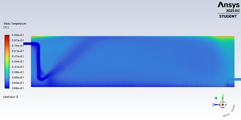
Case study: Temperature stratification in a storage tank
This example illustrates how CFD was used to evaluate thermal stratification and mixing effectiveness in a covered rectangular water storage tank. The study focused on the combined impact of inlet momentum and buoyancy-driven flow, which can lead to persistent layering and low-turnover zones.
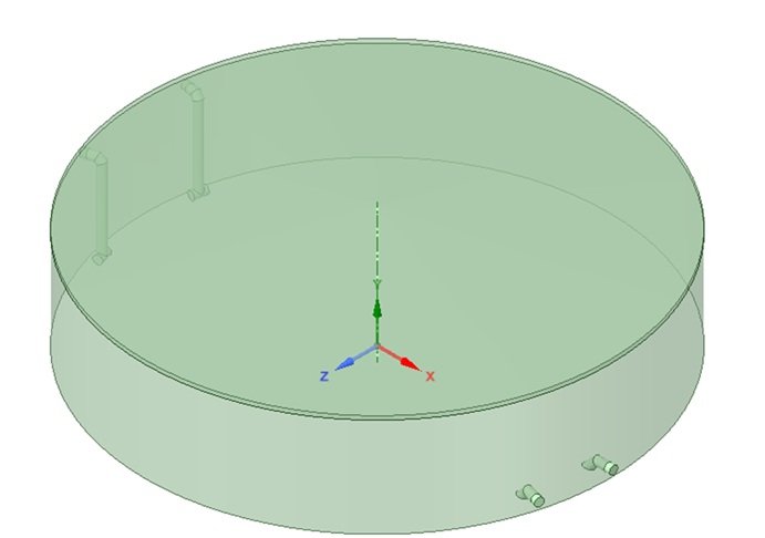
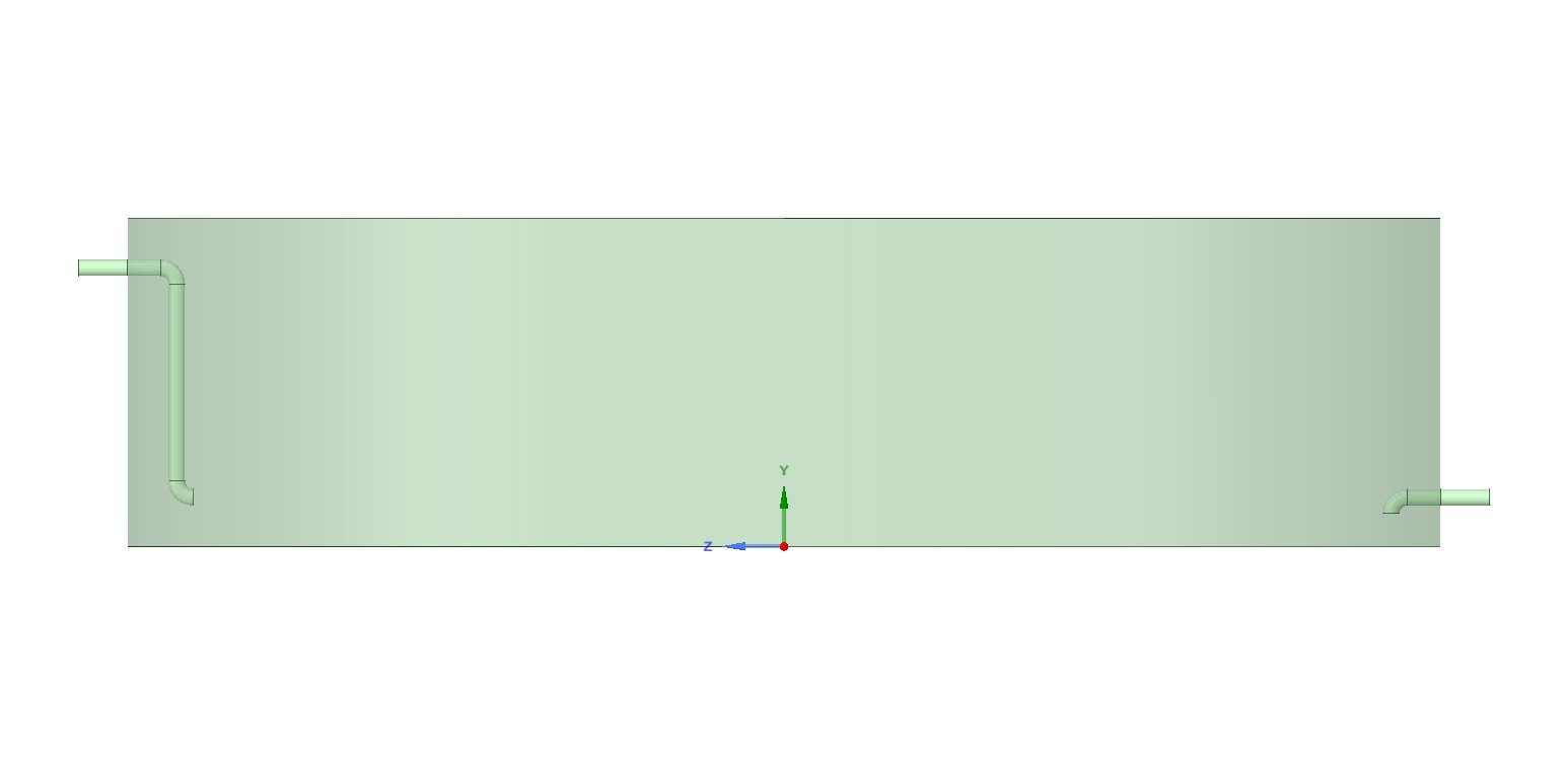
The configuration
- Geometry: covered rectangular tank (long aspect ratio)
- Inlet: side inlet with downward discharge
- Outlet: opposite end, near the bottom
- Key risk: stable thermal layering and stagnant regions away from the inlet path
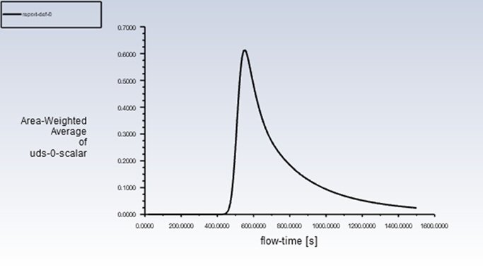
CFD approach
- Tool: ANSYS Fluent (3D)
- Physics: energy equation + gravity (buoyancy enabled)
- Properties: temperature-dependent density
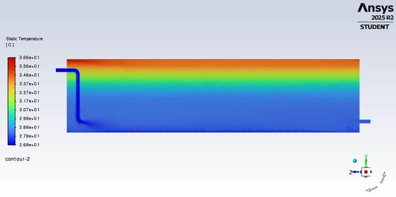
- Outputs: velocity magnitude, static temperature, vertical rake profiles
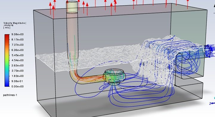
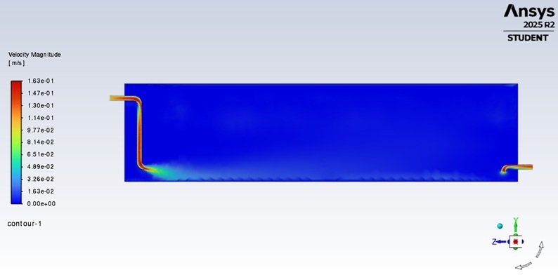
Baseline condition: stratification and limited mixing
Engineering interpretation
- Bulk mixing is limited: circulation is localised near the inlet and does not mobilise the full tank volume.
- Buoyancy stabilises layering: vertical exchange is suppressed, resulting in persistent stratification.
- Operational implication: lower zones may experience higher effective water age and reduced water-quality performance compared to “fully mixed” assumptions.
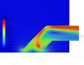
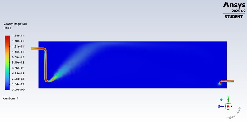
Improved condition: jet-induced circulation to disrupt stratification
An alternative inlet arrangement/operating condition was assessed to promote a stronger circulation pattern and improve vertical mixing.
Typical mitigation options (screened via CFD)
- Inlet upgrade: diffuser / multi-port inlet, or inlet reorientation to drive bulk circulation
- Outlet strategy: review draw-off elevation to improve turnover of lower layers
- Operational actions: periodic turnover/mixing cycles under defined triggers
- Thermal control: roof insulation and heat-gain reduction where relevant
Why work with FluidMechanica?
- Specialist focus on water-sector CFD for tanks, reservoirs and pump intakes
- Strong practical background in EPC design, approvals and operational troubleshooting
- Clear reporting for both technical teams and non-technical decision-makers
- Outputs aligned to design decisions: what to change, why it matters, and expected benefit
Frequently asked questions
When should I commission a CFD study?
Typically during concept or detailed design of tanks/intakes, when revising inlet/outlet layouts, when water-quality performance is uncertain, or when existing assets show poor mixing, stratification, vibration or operational issues.
What information do you need?
Drawings/3D geometry (if available), water levels, flow rates, operating scenarios and any constraints or acceptance criteria. We can start with preliminary data and refine as design progresses.
Do you work only in the UAE?
No. We support clients across the GCC and globally with remote coordination. Models, meetings and reviews are handled online, with clear documentation and version control.
How long does a typical CFD study take?
Scope and complexity vary, but a focused single-tank or intake study typically takes two to four weeks from data receipt to draft report. We confirm programme at the scoping stage.